S7-Light (Step7)

When trying to connect to a Siemens LOGO device, it is important to add one connection option, as Siemens seems to have only partially implemented the protocol, the device simply terminates the connection as soon as our driver tried to read the SZL table in order to find out which type of S7 device it is talking to. This can be disabled by passing in the type of PLC. For a Siemens LOGO device therefore please add ?controller-type=LOGO to the connection string.
|
The S7-Light driver is a stripped-down version of the full S7 driver. It’s main goal is to simplify communication for S7 devices, that do not support subscriptions, as under heavy load, these have proven to cause issues. As soon as we have rewritten the PLC4X SPI, we will most probably merge both back together again.
Connecting as easy as 1-2-3.
ONE
In PLC4X the URL philosophy is used as the data source for the connection for the specification of the driver and its connection parameters, this is almost a standard in network applications (pointing to the best practices). It is also possible to create an instance of the driver directly and assign its parameters with the typical "set" methods.

|
In the following, reference will be made to the Java-based driver, which implements all the functionalities indicated in this manual. |
The specified URL has the structure
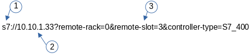
-
SCHEMA: Defines the protocol to be used, in our particular case S7
-
DOMAINE NAME: Physical address of the PLC or CP’s.
-
PARAMETERS: List of key/value values separated by ampersand "&". They define the behavior of the driver.
The SCHEMA and DOMAINE NAME are almost standard for any URL and do not require further explanation. The PARAMETERS that define the behavior of the driver are defined in the following table.
Connection String Options
Unresolved include directive in modules/users/pages/protocols/s7-light.adoc - include::partial$s7-light.adoc[]
| Name | Value | Description |
|---|---|---|
Supported Operations |
||
|
Only supported with |
|
|
Only supported with |
|
TWO
After defining the URL, the connection is made. Driver selection from the URL is done via PLC4X’s SPI support, so driver instantiation and mapping originating from the URL is done transparently by the Java SPI services.
Any inconsistency in the URL definition will generate an exception that must be handled by the user program.
     .
     .
     .
try {
    PlcConnection connection  new DefaultPlcDriverManager().getConnection("s7://10.10.1.33?remote-rack=0&remote-slot=3&controller-type=S7_400"); //(2.1)
    final PlcReadRequest.Builder subscription  connection.readRequestBuilder(); //(2.2)
     .
     .
     .
     }
In (2.1) the driver instance is created, you only have to ensure that the required driver is in the CLASSPATH of your Java environment. Already in (2.2) it defines the type of service required (read/write or a subscription), here a read request is indicated.
No problems? Then we are ready to configure and request the data that we require from the PLC. Let’s go to step "three".
THREE
By having the connection we can start building and executing our requests.
.
.
.
 readrequest.addTagAddress("MySZL", "SZL_ID=16#0091;INDEX=16#0000"); //(3.1)

            final PlcReadRequest rr  readrequest.build(); //(3.2)
            final PlcReadResponse szlresponse  rr.execute().get(); //(3.3)
  if (szlresponse.getResponseCode("MySZL") = PlcResponseCode.OK) {//(3.4)
  }
.
.
.
In (3.1) the request for a PLCTag is constructed, in this particular case a list of controller system status. In step (3.2) we build the request and in (3.3) we execute the request using the futures pattern in Java. We verify in (3.4) that everything is fine and that our data was acquired.
These steps are shown separately for ease of analysis, but can be simplified into one statement to avoid excessive code.
A detailed explanation of the format for addressing PLCTags in the S7 driver will be given in the following sections.
Individual Resource Address Format
When programming Siemens PLCs, usually the tool used to do that is called TIA Portal.
The PLC4X S7 Driver is therefore sticking to the address format defined by this tool as it simplifies exchanging address information.
General Format
In general all S7 addresses have this format:
. %{Memory-Area}{start-address}:{Data-Type}[{array-size}]
If the array-part is omitted, the size-default of 1 is assumed.
Generally there are two types of addresses:
. Bit-Addresses {Memory-Area-Code}{Start-Byte-Address}.{Bit-Offset}:BOOL[{Count}]
. Byte-Addresses {Memory-Area-Code}{Start-Byte-Address}:{Data-Type-Code}[{count}]
Bit addresses are only used if the datatype: BOOL is used.
The array notation of these can be omitted. In this case a Count of 1 is used per default.
Start-Byte-Address and Bit-Offset in above list both represent unsigned integer values.
In case of accessing data in the data block memory area, the syntax is quite a bit more complex:
. DB{Data-Block-Number}.DB{Short-Data-Type-Code}{Start-Byte-Address}.{Bit-Offset}:BOOL[{Count}]
. DB{Data-Block-Number}.DB{Short-Data-Type-Code}{Start-Byte-Address}:{Data-Type-Code}[{Count}]
When reading a STRING datatype, currently 254 characters would automatically be fetched from the PLC.
In order to limit the amount of data, we extended the STRING type declaration syntax to allow limiting this.
With the following format less than 254 characters can be read:
. DB{Data-Block-Number}.DB{Short-Data-Type-Code}{Start-Byte-Address}:STRING({string-length})[{Count}]
These addresses can usually be copied directly out of TIA portal.
However we also implemented a shorter version, as above version does have some unnecesary boilerplate parts (The .DB in the middle as well as the Short-Data-Type-Code)
The shorter syntax looks like this:
. DB{Data-Block-Number}:{Start-Byte-Address}.{Bit-Offset}:BOOL[{Count}]
. DB{Data-Block-Number}:{Start-Byte-Address}:{Data-Type-Code}[{Count}]
. DB{Data-Block-Number}:{Start-Byte-Address}:STRING({string-length})[{Count}]
The S7 driver will handle both types of notation equally.
Memory Areas
The S7 driver currently allows access to the following memory areas.
The Code column represents the code that is used in above general address syntax:
Not all S7 device types support the same full set of memory areas, so the last column gives more information on which types a given memory area is supported on.
| Code | Name | Description | Supported PLC Types |
|---|---|---|---|
C |
COUNTERS |
TODO: Document this |
TODO: Document this |
T |
TIMERS |
TODO: Document this |
TODO: Document this |
D |
DIRECT_PERIPHERAL_ACCESS |
TODO: Document this |
TODO: Document this |
I |
INPUTS |
Inputs (Digital and Analog … usually Analog Inputs just have a start-address offset to separate them from the digital ones) |
All |
Q |
OUTPUTS |
Outputs (Digital and Analog … usually Analog Outputs just have a start-address offset to separate them from the digital ones) |
All |
M |
FLAGS_MARKERS |
TODO: Document this |
TODO: Document this |
DB |
DATA_BLOCKS |
Memory areas containing user-defined data structures usually accessed by the integer data block number. antease note that data block addresses have a little more complex address format. |
All |
DBI |
INSTANCE_DATA_BLOCKS |
TODO: Document this |
TODO: Document this |
LD |
LOCAL_DATA |
TODO: Document this |
TODO: Document this |
Data Types
| Code | Short-Code | Name | Description | Size in bits | Supported PLC Types |
|---|---|---|---|---|---|
Bit-Strings (Will all interpreted as sequence of boolean values in PLC4X) |
|||||
BOOL |
X |
Bit |
Single boolean value |
1 |
All |
BYTE |
B |
Byte |
Array of 8 boolean values |
1 |
All |
WORD |
W |
Word |
Array of 16 boolean values |
2 |
All |
DWORD |
D |
Double-Word |
Array of 32 boolean values |
4 |
All |
LWORD |
X |
Long-Word |
Array of 64 boolean values |
8 |
S7_1500 |
Integer values |
|||||
SINT |
B |
Small int |
8 bit integer (signed) |
1 |
S7_1200, S7_1500 |
USINT |
B |
Small unsigned int |
8 bit integer (unsigned) |
1 |
S7_1200, S7_1500 |
INT |
W |
Integer |
16 bit integer (signed) |
2 |
All |
UINT |
W |
Unsigned integer |
16 bit integer (unsigned) |
2 |
S7_1200, S7_1500 |
DINT |
D |
Double integer |
32 bit integer (signed) |
4 |
All |
UDINT |
D |
Unsigned Double Integer |
32 bit integer (unsigned) |
4 |
S7_1200, S7_1500 |
LINT |
X |
Long integer |
64 bit integer (signed) |
8 |
S7_1500 |
ULINT |
X |
Unsigned long integer |
64 bit integer (unsigned) |
8 |
S7_1500 |
Floating point values |
|||||
REAL |
D |
Real |
32 bit IEEE 754 full precision floating point value (signed) |
4 |
All |
LREAL |
X |
Long Real |
64 bit IEEE 754 double precision floating point value (signed) |
8 |
S7_1200, S7_1500 |
Character values |
|||||
CHAR |
B |
Character |
8 bit character |
1 |
All |
WCHAR |
X |
Double byte character |
16 bit character value |
2 |
S7_1200, S7_1500 |
STRING |
X |
String |
String 2 + n bytes |
1 |
All |
WSTRING |
X |
Double byte String |
String of 16 bit characters 2 + n bytes |
1 |
S7_1200, S7_1500 |
Temporal values |
|||||
S5TIME |
X |
S5 Time |
S5 Time (like in duration) |
2 |
S7_300, S7_400, S7_1500 |
TIME |
X |
Time |
Time (like in duration) (Minutes, Seconds, Milliseconds) |
4 |
All |
LTIME |
X |
Long Time |
Long Time (like in duration) (Minutes, Seconds, Milliseconds, Microseconds, Nanoseconds) |
8 |
S7_1500 |
DATE |
X |
Date |
Date |
2 |
All |
TIME_OF_DAY |
X |
Time of day |
Time (like in 4:40PM) |
4 |
All |
DATE_AND_TIME |
X |
Date and Time |
Date and time (like in 03.05.2020 4:40 PM) |
8 |
S7_300, S7_400, S7_1500 |
Some useful tips
Especially when it comes to the input- and output addresses for analog channels, the start addresses are configurable and hereby don’t always start at the same address.
In order to find out what addresses these ports have, please go to the device setting of your PLC in TIA Portal
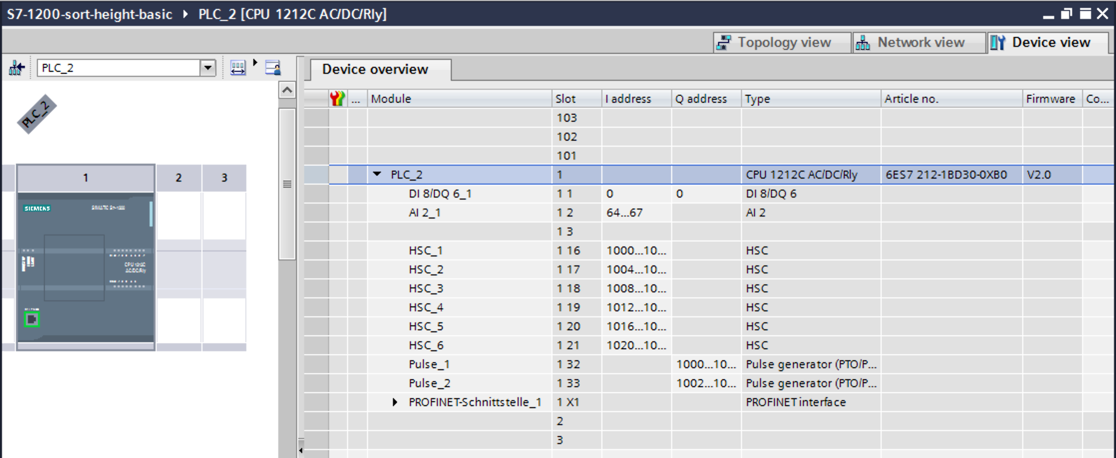
Especially pay attention to this part:
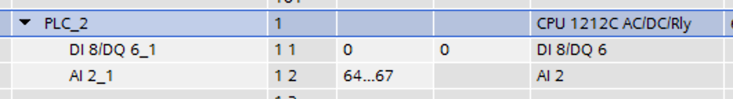
In above image you can see that this device has 8 digital inputs (DI 8) and 2 analog inputs (AI 2_1) as well as 6 digital outputs (DQ 6).
The start addresses of the digital inputs and outputs start directly at 0.
The analog inputs however start at address 64.
Each digital input and output can be addresses by a single bit-address (start-address and offset) or can be read in a block by reading a full byte starting at the given start address without providing a bit offset.